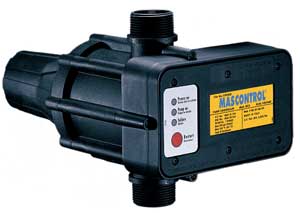
Product Description:
- Maintains constant pressure and flow
- Eliminates pump pressure switch
- Built-in pressure and flow switch
- Built-in check valve
- Built-in dry-run protection
- Assists in absorbing water hammer
- Increases pump life
|
- Dual voltage 115V / 230V A/C
- Choose from 22, 32 or 42 PSI models
- No adjustment or maintenance required
- Simple installation saves space and time
- Can be used with or without pressure tank
- All stainless steel internal construction
|
Technical Specifications:
| Single phase power-supply voltage |
115V / 230V A/C |
| Voltage variation tolerance |
± 10% |
| Frequency |
50 / 60 Hz |
| Full load amp rating |
115V A/C 16 FLA |
| Full load amp rating |
230V A/C 20 FLA |
| Electronic box |
NEMA 12 enclosure |
| Threaded conduit connections |
.5'' NPT |
| Max working pressure |
145 PSI |
| Max working temperature |
149 °F |
NEMA 12
The electronic board is completely dust-proof.
MAXIMUM OPERATING TEMPERATURE 149 °F
The device is built to work in an environment in which the temperature may reach 149 °F.
DEVICE COMPONENTS:
| Three Different Factory Preset Cut-In Pressures |
| PSI of Model |
22 PSI |
32 PSI |
42 PSI |
| Pump Minimum PSI |
45 PSI |
55 PSI |
70 PSI |
| Max Elevation from Controller to Tap |
50 Feet |
70 Feet |
90 Feet |
Construction Details:
Body, non-return valve, rear part and knob are molded in 30% fibreglass reinforced polyamide 6 (PA6GF30).
This allows for obtaining a high resistance to wear and pressure.
The diaphragm is molded in EPDM ( Ethylene Propylene Diene Monomer ).
This guarantees exceptional reliability and durability.
The flow valve is in stainless steel (AISI 304).
The dimensional stability of the metal guarantees the operation of the components .
The spring is made in UNI 3823 steel wire.
The stabilization process guarantees the operation of the pressure switch, essential for the pump start-up precision and the system pressure adjustment. The dimensions and structure of the same allow for considerably reducing the effects of water hammering.
The box containing the electrical part is molded in shockproof self-extinguishing PBT.
The use of prime materials and top-of-the-range components allows for achieving high levels of dimensional stability, resistance to wear and bursting, and duration over time. |
Installation:
The device can be mounted either directly onto the pump or between the pump and the first service.
If the input pressure of the device exceeds 145 PSI, install a pressure reducer between the pump and the device itself.
No tap can be mounted between the pump and the device.
It is essential to mount the device with the flow arrows pointing upwards (fig. A). |
|
 |
It is recommended to connect the output of the device to the system by means of a ball valve and flexible tube (fig. B).
Before starting the device check that the pump is correctly primed. |
Electrical Connections:
Installation Wiring Diagram - 115V A/C 2-Wire Pumps
For 115V A/C motors exceeding 16 full load amps, use magnetic starter to avoid damage to MASCONTROL. See separate magnetic starter wiring diagram. |
Installation Wiring Diagram - 230V A/C Single Phase 2-Wire Pumps
For 230V A/C motors exceeding 20 full load amps, use magnetic starter to avoid damage to MASCONTROL. See separate magnetic starter wiring diagram. |
| Pressure Loss Chart |
| Flow rate |
GPM |
5 |
10 |
15 |
18 |
20 |
25 |
30 |
35 |
40 |
| MCA ( 1” ) |
Pressure Loss (PSI) |
0.5 |
1.5 |
4 |
6.5 |
8.5 |
|
|
|
|
| MCB ( 1.25” ) |
Pressure Loss (PSI) |
|
0.5 |
1.5 |
2.5 |
3.5 |
5.5 |
7.5 |
10 |
12.5 |
| Pressure Loss Chart with a Bypass Application |
| Flow rate |
GPM |
20 |
30 |
40 |
50 |
60 |
70 |
80 |
|
|
| MCA x 1'' |
Pressure Loss (PSI) |
3 |
5 |
9 |
14 |
19 |
/ |
/ |
|
|
| MCB x 1.25'' |
Pressure Loss (PSI) |
2 |
2 |
3 |
5 |
8 |
10 |
12 |
|
|
| MCB x 1.5'' |
Pressure Loss (PSI) |
2 |
2 |
3 |
4 |
6 |
7 |
8 |
|
|
Use MASCONTROL in bypass when friction loss is excessive.
The main bypass piping must not exceed 1.5”, while the system pipe could be bigger. |
For minimal delivery demands, the application of a small expansion tank downstream from the MASCONTROL allows for reducing the pump start-ups.
(Example: a glass of water, ice-making machine, inverse osmosis systems, or old systems with small losses).
It is recommended to preload the expansion tank at a slightly lower value than the restart pressure calibration value of the device.
(Example: MASCONTROL calibrated at 42 PSI, tank preloaded at approximately 40 PSI).
|
|


